4x4 Keypad Interfacing With MSP-EXP430G2 TI Launchpad
Introduction
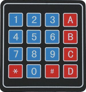
4x4 Keypad
Keypad is used as an input device to read the key pressed by user and to process it.
4x4 keypad consists of 4 rows and 4 columns. Switches are placed between the rows and columns.
A key press establishes a connection between the corresponding row and column, between which the switch is placed.
For more information about keypad and how to use it, refer the topic 4x4 Keypad in the sensors and modules section.
Interfacing Diagram
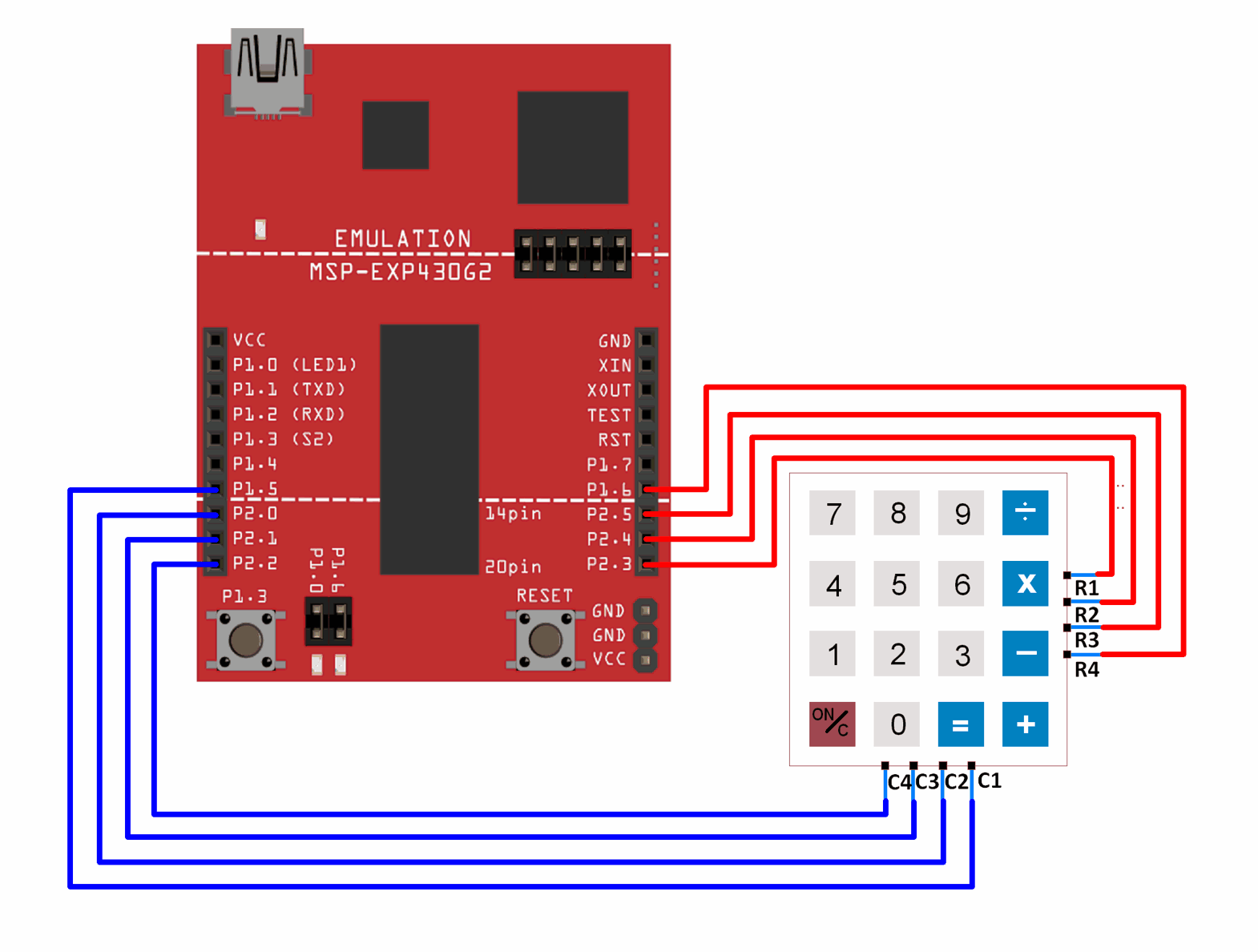 Interfacing 4x4 Keypad with MSP-EXP430G2 TI Launchpad
Example
Reading the key pressed on 4x4 keypad and displaying it on the serial terminal of Energia.
Here, we will be using the Keypad library by Mark Stanley and Alexander Brevig.
Extract the library and add it to the libraries folder path of Energia IDE.
For information about how to add a custom library to the Energia IDE and use examples from it, refer Adding Library To Energia IDE in the Basics section.
Once the library has been added to the Energia IDE, open the IDE and open the example sketch for CustomKeypad from the library added.
Tread Carefully : MSP-EXP430G2 TI Launchpad board has a RAM of 512 bytes which is easily filled, especially while using different libraries. There are times when you need the Serial buffer to be large enough to contain the data you want and you will have to modify the buffer size for the Serial library. While doing such things, we must ensure that the code does not utilize more than 70% RAM. This could lead to the code working in an erratic manner, working well at times and failing miserably at others.
There are times when the RAM usage may exceed 70% and the codes will work absolutely fine, and times when the code will not work even when the RAM usage is 65%.
In such cases, a bit of trial and error with the buffer size and/or variables may be necessary.
Sketch for 4x4 Keypad
/* @file CustomKeypad.pde
|| @version 1.0
|| @author Alexander Brevig
|| @contact alexanderbrevig@gmail.com
||
|| @description
|| | Demonstrates changing the keypad size and key values.
|| #
*/
#include <Keypad.h>

const byte ROWS = 4; //four rows
const byte COLS = 4; //four columns
//define the cymbols on the buttons of the keypads
char hexaKeys[ROWS][COLS] = {
  {'0','1','2','3'},
  {'4','5','6','7'},
  {'8','9','A','B'},
  {'C','D','E','F'}
};
byte rowPins[ROWS] = {11, 12, 13, 14}; //connect to the row pinouts of the keypad
byte colPins[COLS] = {7, 8, 9, 10}; //connect to the column pinouts of the keypad

//initialize an instance of class NewKeypad
Keypad customKeypad = Keypad( makeKeymap(hexaKeys), rowPins, colPins, ROWS, COLS);

void setup(){
  Serial.begin(9600);
}

void loop(){
  char customKey = customKeypad.getKey();

  if (customKey){
    Serial.println(customKey);
  }
}
Video
Function Used
1. makeKeymap(keys)
- This function is used to initialize the internal keymap to be equal to the user defined key map (in function syntax given above, keys).
2. Keypad customKeypad = Keypad( makeKeymap(keys), rowPins, colPins, rows, cols)
- This defines an object customKeypad of the class Keypad and initializes it.
- rowPins and colPins are the pins on MSP-EXP430G2 TI Launchpad board to which the rows and columns of the keypad are connected to.
- rows and cols are the number of rows and columns the keypad has.
3. customKeypad.getKey()
- This function is used to identify which key is pressed on the keypad.
Note
byte rowPins[ROWS] = {R1, R2, R3, R4}; /* connect to the row pinouts of the keypad */
byte colPins[COLS] = {C1, C2, C3, C4}; /* connect to the column pinouts of the keypad */
If you do not connect the pins according to this function, the key press identification will not give results according to the keypad you have defined.
Word of Caution : The example sketch Custom Keypad included in the Keypad library is written for Arduino board and hence should not be uploaded as it is to the MSP-EXP430G2 TI Launchpad board. Doing so may give errors and might even damage the board in some cases. Change the pins specified for rows and columns in the example sketch as shown in the above sketch and make connections as shown in the interfacing diagram. Avoid using pins 3 (P1_1) and 4 (P1_2) of the MSP-EXP430G2 TI Launchpad board while using the serial monitor as it may cause an issue (because Serial monitor also uses these pins for communication).
1-Wire interfacing of Keypad With MSP-EXP430G2 TI Launchpad
The above shown interfacing consumes 8 GPIO pins of the MSP-EXP430G2 TI Launchpad board. By using the 1-wire interfacing method for keypad, we can achieve the same result as above using just 1 GPIO pin.
This method makes use of simple voltage divider concept to generate different voltages for each key pressed.
Let’s see how to interface keypad to MSP-EXP430G2 TI Launchpad using a single GPIO pin.
Interfacing Diagram
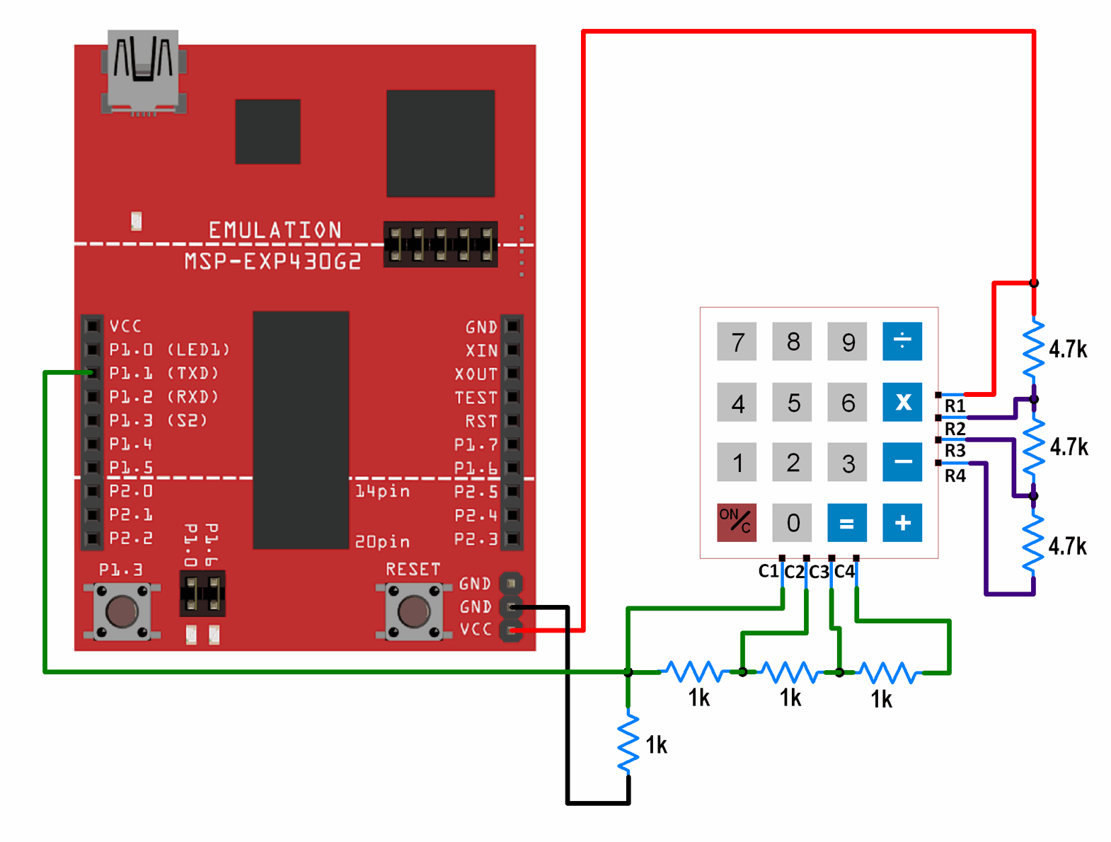
1-Wire Interfacing of Keypad with MSP-EXP430G2 TI Launchpad
Sketch
void setup() {
  Serial.begin(9600); /* Define baud rate for serial communication */
}

void loop() {
  int adc_val;
  adc_val = analogRead(A1); /* Read input from keypad */
  if (adc_val>850)
  {
    Serial.print("Key Pressed : ");
    Serial.println("0");
    delay(100);
  }
  else if ( adc_val>450  && adc_val<550)
  {
    Serial.print("Key Pressed : ");
    Serial.println("1");
    delay(100);
  }
  else if ( adc_val>330  && adc_val<370)
  {
    Serial.print("Key Pressed : ");
    Serial.println("2");
    delay(100);
  }
  else if ( adc_val>260  && adc_val<280)
  {
    Serial.print("Key Pressed : ");
    Serial.println("3");
    delay(100);
  }
  else if ( adc_val>190  && adc_val<210)
  {
    Serial.print("Key Pressed : ");
    Serial.println("4");
    delay(100);
  }
  else if ( adc_val>165  && adc_val<185)
  {
    Serial.print("Key Pressed : ");
    Serial.println("5");
    delay(100);
  }
  else if ( adc_val>148  && adc_val<164)
  {
    Serial.print("Key Pressed : ");
    Serial.println("6");
    delay(100);
  }
  else if ( adc_val>132  && adc_val<147)
  {
    Serial.print("Key Pressed : ");
    Serial.println("7");
    delay(100);
  }
  else if ( adc_val>=121  && adc_val<=131)
  {
    Serial.print("Key Pressed : ");
    Serial.println("8");
    delay(100);
  }
  else if ( adc_val>=115  && adc_val<=120)
  {
    Serial.print("Key Pressed : ");
    Serial.println("9");
    delay(100);
  }
  else if ( adc_val>=107  && adc_val<=113)
  {
    Serial.print("Key Pressed : ");
    Serial.println("A");
    delay(100);
  }
  else if ( adc_val>=100  && adc_val<=106)
  {
    Serial.print("Key Pressed : ");
    Serial.println("B");
    delay(100);
  }
  else if ( adc_val>=95  && adc_val<=99)
  {
    Serial.print("Key Pressed : ");
    Serial.println("C");
    delay(100);
  }
  else if ( adc_val>=90  && adc_val<=94)
  {
    Serial.print("Key Pressed : ");
    Serial.println("D");
    delay(100);
  }
  else if ( adc_val>=87  && adc_val<=89)
  {
    Serial.print("Key Pressed : ");
    Serial.println("E");
    delay(100);
  }
  else if( adc_val>=82  && adc_val<=85)
  {
    Serial.print("Key Pressed : ");
    Serial.println("F");
    delay(100);
  }
  else
  {

  }
  delay(100);
}
Video
Word of Caution : The ADC values used for deciding the key presses have been found out practically. You might need to find out the ADC values practically. These values have been found out for the resistor combination shown in the interfacing diagram. If you use other resistor values, the above code will give faulty output. If you decide to use other resistor values, you will have to find out the ADC values for each key press and make changes accordingly in the code.
Supporting Files
Source Code
- Keypad_1_Wire_Interfacing_With_TI_Launchpad_INO Download 62
Attached File
- Keypad Library Download 69
No comments:
Post a Comment