DHT11 Sensor Interfacing with AVR ATmega16/ATmega32.
Introduction
DHT11 is a single wire digital humidity and temperature sensor, which provides humidity and temperature values serially.
It can measure relative humidity in percentage (20 to 90% RH) and temperature in degree Celsius in the range of 0 to 50°C.
It has 4 pins of which 2 pins are used for supply, 1 is not used and the last one is used for data.
The data is the only pin used for communication. Pulses of different TON and TOFF are decoded as logic 1 or logic 0 or start pulse or end of frame.
For more information about DHT11 sensor and how to use it, refer the topic DHT11 sensor in the sensors and modules topic.
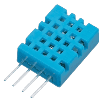
DHT11 Sensor
Circuit diagram
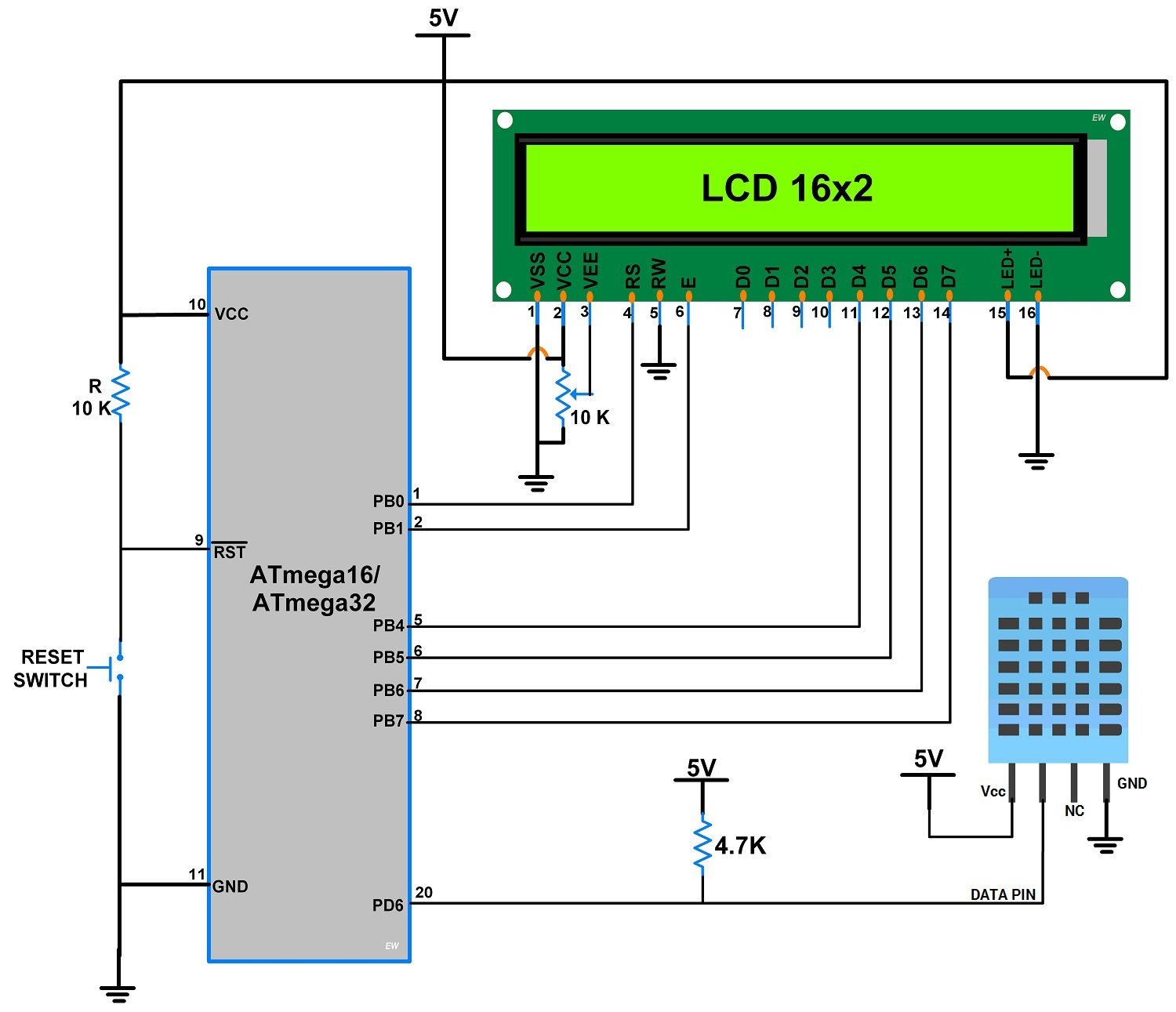
Interfacing DHT11 Sensor With AVR ATmega16/ATmega32
- The above circuit diagram shows interfacing of AVR ATmega16/ATmega32 to the DHT11 sensor.
- In that, LCD is interfaced to PORTB in 4-bit mode, and a DHT11 sensor is connected to PD6 (Pin no 20).
Programming of DHT11
- First initialize the LCD16x2_4bit library.
- Define pin no. to interface DHT11 sensor, in our program we define PD6 (Pin no. 20).
- Send the start pulse to DHT11 sensor, making low to high.
- Receive the response pulse from the DHT11 sensor.
- After receiving the response, receive 40-bit data serially from DHT11 sensor.
- Display this received data on LCD16x2 along with error indication.
Code
/*
 * ATmega16_DHT11_Project_File.c
 *
 * http://www.electronicwings.com
 */

#include <avr/io.h>
#include <stdlib.h>
#include <stdio.h>
#include "LCD16x2_4bit.h"
#define DHT11_PIN 6
uint8_t c=0,I_RH,D_RH,I_Temp,D_Temp,CheckSum;

void Request()    /* Microcontroller send start pulse/request */
{
 DDRD |= (1<<DHT11_PIN);
 PORTD &= ~(1<<DHT11_PIN); /* set to low pin */
 _delay_ms(20);   /* wait for 20ms */
 PORTD |= (1<<DHT11_PIN); /* set to high pin */
}

void Response()    /* receive response from DHT11 */
{
 DDRD &= ~(1<<DHT11_PIN);
 while(PIND & (1<<DHT11_PIN));
 while((PIND & (1<<DHT11_PIN))==0);
 while(PIND & (1<<DHT11_PIN));
}

uint8_t Receive_data()   /* receive data */
{
 for (int q=0; q<8; q++)
 {
  while((PIND & (1<<DHT11_PIN)) == 0);  /* check received bit 0 or 1 */
  _delay_us(30);
  if(PIND & (1<<DHT11_PIN))/* if high pulse is greater than 30ms */
  c = (c<<1)|(0x01); /* then its logic HIGH */
  else   /* otherwise its logic LOW */
  c = (c<<1);
  while(PIND & (1<<DHT11_PIN));
 }
 return c;
}

int main(void)
{
 char data[5];
 lcdinit();   /* Initialize LCD */
 lcd_clear();   /* Clear LCD */
 lcd_gotoxy(0,0);  /* Enter column and row position */
 lcd_print("Humidity =");
 lcd_gotoxy(0,1);
 lcd_print("Temp = ");

    while(1)
 {
  Request();  /* send start pulse */
  Response();  /* receive response */
  I_RH=Receive_data(); /* store first eight bit in I_RH */
  D_RH=Receive_data(); /* store next eight bit in D_RH */
  I_Temp=Receive_data(); /* store next eight bit in I_Temp */
  D_Temp=Receive_data(); /* store next eight bit in D_Temp */
  CheckSum=Receive_data();/* store next eight bit in CheckSum */

  if ((I_RH + D_RH + I_Temp + D_Temp) != CheckSum)
  {
   lcd_gotoxy(0,0);
   lcd_print("Error");
  }

  else
  {
   itoa(I_RH,data,10);
   lcd_gotoxy(11,0);
   lcd_print(data);
   lcd_print(".");

   itoa(D_RH,data,10);
   lcd_print(data);
   lcd_print("%");

   itoa(I_Temp,data,10);
   lcd_gotoxy(6,1);
   lcd_print(data);
   lcd_print(".");

   itoa(D_Temp,data,10);
   lcd_print(data);
   lcddata(0xDF);
   lcd_print("C ");

   itoa(CheckSum,data,10);
   lcd_print(data);
   lcd_print(" ");
  }

 _delay_ms(10);
 }
}
No comments:
Post a Comment