LCD 16x2 custom character display using LPC2148
Introduction
 LCD 16x2 Display
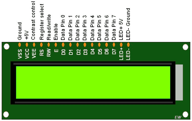
LCDs (Liquid Crystal Displays) are used for displaying status or parameters in embedded systems.
LCD 16x2 is a 16-pin device which has 8 data pins (D0-D7) and 3 control pins (RS, RW, EN). The remaining 5 pins are for supply and backlight for the LCD.
The control pins help us configure the LCD in command mode or data mode. They also help configure read mode or write mode and also when to read or write.
LCD 16x2 can be used in 4-bit mode or 8-bit mode depending on the requirement of the application. In order to use it we need to send certain commands to the LCD in command mode and once the LCD is configured according to our need, we can send the required data in data mode to display on it.
For more information about LCD 16x2 and how to use it, refer the topic LCD 16x2 display module in the sensors and modules section.
Interfacing Diagram
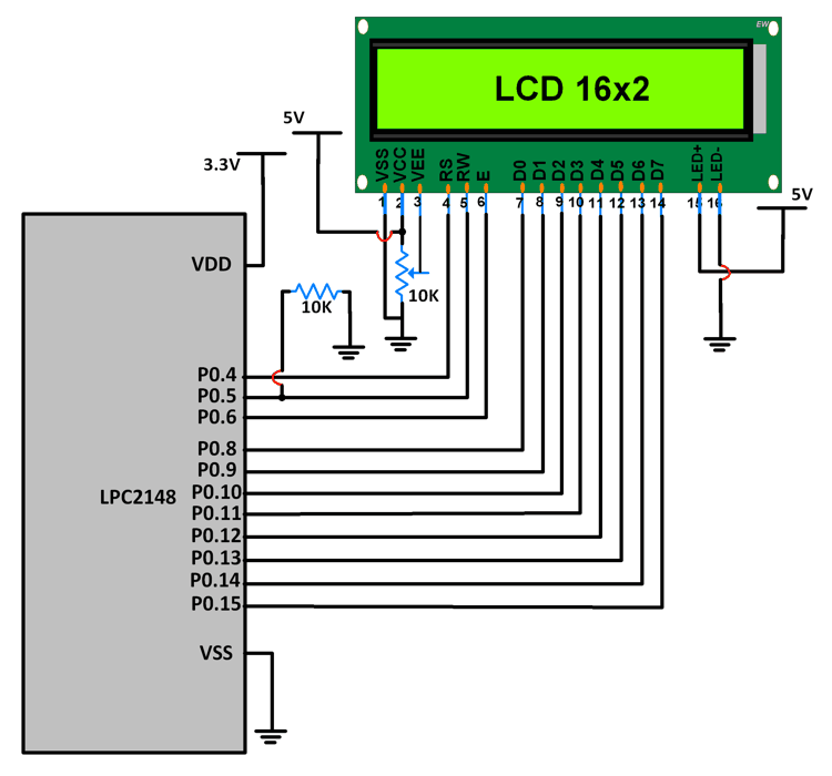 Interfacing 16x2 LCD with LPC2148
LCD Data pins D0-D7 are connected to pins P0.8-P0.15 of Port 0.
LCD control pins RS, RW and EN are connected to P0.4, P0.5 P0.6 respectively.
Building LCD custom character is basically the process of storing the 5x8 dot matrix pattern of the character in the CGRAM in order to be used later.
User can maintain up to 8 different characters in the CGRAM at 8 different locations.
Function for Building Custom Character
void LCD_BUILD_CUST_CHAR(unsigned char location, unsigned char *data)
{
 uint8_t i;
 if(location<8)
 {
  LCD_CMD((0x40 + (8*location))); /* CGRAM location */
  for(i=0;i<8;i++)
  LCD_CHAR(data[i]); /* Data to be stored at CGRAM location */
 }
}
Location can be a number from 0 to 7 which stores the character in CGRAM space (0x40 to 0x7F).
Once the character has been built, it can be accessed by referring to its location and printed like other characters.
Example
A program to display user defined characters on LCD 16x2.
Program
/*
16x2 LCD custom character generation using LPC2148(ARM7)
http://www.electronicwings.com/arm7/lcd-16x2-custom-character-display-using-lpc2148
*/
#include <lpc214x.h>
#include <stdint.h>
#include <stdlib.h>
#include <stdio.h>
void delay_ms(uint16_t j) /* Function for delay in milliseconds */
{
uint16_t x,i;
for(i=0;i<j;i++)
{
for(x=0; x<6000; x++); /* loop to generate 1 millisecond delay with Cclk = 60MHz */
}
}
void LCD_CMD(char command)
{
IO0PIN = ( (IO0PIN & 0xFFFF00FF) | (command<<8) ); /* Put command on data pins */
delay_ms(2);
IO0SET = 0x00000040; /* EN = 1 */
IO0CLR = 0x00000030; /* RS = 0, RW = 0 */
delay_ms(2);
IO0CLR = 0x00000040; /* EN = 0, RS and RW unchaned(i.e. RS = RW = 0) */
delay_ms(5);
}
void LCD_INIT(void)
{
IO0DIR = 0x0000FFF0; /* P0.8 to P0.15 LCD Data. P0.4,5,6 as RS RW and EN */
delay_ms(20);
LCD_CMD(0x38); /* Initialize lcd */
LCD_CMD(0x0C); /* Display on cursor off */
LCD_CMD(0x06); /* Auto increment cursor */
LCD_CMD(0x01); /* Display clear */
LCD_CMD(0x80); /* First line first position */
}
void LCD_STRING (char* msg)
{
uint8_t i=0;
while(msg[i]!=0)
{
IO0PIN = ( (IO0PIN & 0xFFFF00FF) | (msg[i]<<8) ); /* Put msg[i] on data pins */
IO0SET = 0x00000050; /* RS = 1, , EN = 1 */
IO0CLR = 0x00000020; /* RW = 0 */
delay_ms(2);
IO0CLR = 0x00000040; /* EN = 0, RS and RW unchanged(i.e. RS = 1, RW = 0) */
delay_ms(5);
i++;
}
}
void LCD_CHAR (char msg)
{
IO0PIN = ( (IO0PIN & 0xFFFF00FF) | (msg<<8) ); /* Put msg on data pins */
delay_ms(2);
IO0SET = 0x00000050; /* RS = 1, , EN = 1 */
IO0CLR = 0x00000020; /* RW = 0 */
delay_ms(2);
IO0CLR = 0x00000040; /* EN = 0, RS and RW unchanged(i.e. RS = 1, RW = 0) */
delay_ms(5);
}
void LCD_BUILD_CUST_CHAR(unsigned char location, unsigned char *data)
{
uint8_t i;
if(location<8)
{
LCD_CMD((0x40 + (8*location))); /* CGRAM location */
for(i=0;i<8;i++)
LCD_CHAR(data[i]); /* Data to be stored at CGRAM location */
}
}
int main(void)
{
LCD_INIT();
unsigned char cust_char0[8] = {0x00, 0x1F, 0x0A, 0x0A, 0x0A, 0x0A, 0x09, 0x00}; /* Pi */
unsigned char cust_char1[8] = {0x11, 0x19, 0x1D, 0x1F, 0x1F, 0x19, 0x11, 0x00}; /* Diode */
unsigned char cust_char2[8] = {0x12, 0x14, 0x18, 0x10, 0x18, 0x15, 0x13, 0x17}; /* Transistor */
LCD_BUILD_CUST_CHAR(3,cust_char0);
LCD_BUILD_CUST_CHAR(4,cust_char1);
LCD_BUILD_CUST_CHAR(5,cust_char2);
LCD_CMD(0x80);
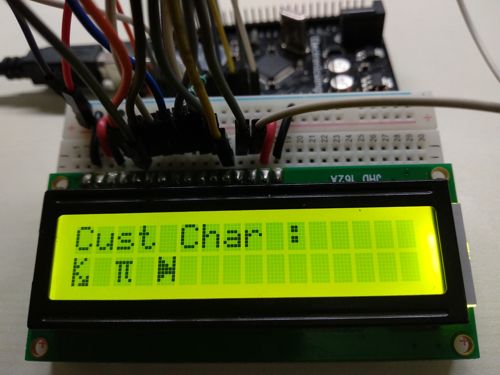
LCD_STRING("Cust Char :");
LCD_CMD(0xC0);
LCD_CHAR(5); /* Print custom character stored at location 5 */
LCD_CHAR(' ');
LCD_CHAR(3); /* Print custom character stored at location 3 */
LCD_CHAR(' ');
LCD_CHAR(4); /* Print custom character stored at location 4 */
LCD_CHAR(' ');
return 0;
}
Output
No comments:
Post a Comment