Nokia5110 graphical display interfacing with AVR ATmega16/ATmega32
Introduction
Nokia5110 is a graphical display that can display text, images and various patterns.
It has a resolution of 48x84 and comes with a backlight.
It uses SPI communication to communicate with a microcontroller.
Data and commands can be sent through microcontroller to the display to control the display output.
It has 8 pins.
For more information about Nokia5110 display and how to use it, refer the topic Nokia5110 Graphical Display in the sensors and modules section.
For information on SPI in ATmega 16, refer the topic on SPI in AVR ATmega16/ATmega32 in the ATmega inside section.
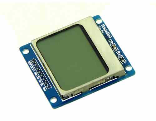
Nokia 5110 Display
Circuit diagram
- Following circuit diagram shows the complete interfacing of Atmega16 / 32 to nokia5110 display.
- The pin connection is, reset pin of display is connected to the PB0 pin, CE is connected to SS(PB4) pin, DC is connected to PB1 pin, Din is connected to MOSI(PB5) pin, clk is connected to SCLK(PB7) pin of microcontroller.

Interfacing Nokia 5110 Display With AVR ATmega16/ ATmega32
Programming for Nokia5110 Display
- In the coding, first step is to initialize the SPI_Master_H_file.h library and N5110.h header files.
- SPI_Master_H_file.h file contains definition of SPI initialization.
- N5110.h file contains all the characters and symbols array definition.
Initialization of Nokia5110
- In initialization of Nokia5110, the first step is to reset the display by sending low to high pulse to reset pin.
- Send command 0x21H for set the command in additional mode (H=1).
- Then set VOP=5V by sending command 0xC0H.
- Set the temp. coefficient to 3 by sending 0x07H.
- Set the voltage bias system using 0x13 command, it is recommended for n=4 and 1:48 mux rate.
- Send the command 0x20 for basic mode operation (H=0).
- And then send 0x0C for normal mode operation.
void N5110_init()
{
 N5110_Reset();  /* reset the display */
 N5110_Cmnd(0x21);  /* command set in addition mode */
 N5110_Cmnd(0xC0);  /* set the voltage by sending C0 means VOP = 5V */
 N5110_Cmnd(0x07);  /* set the temp. coefficient to 3 */
 N5110_Cmnd(0x13);  /* set value of Voltage Bias System */
 N5110_Cmnd(0x20);  /* command set in basic mode */
 N5110_Cmnd(0x0C);  /* display result in normal mode */
}
Command write function
- For command operation make DC pin low.
- Enable the slave select pin.
- Send the command on SPI data register.
- Then DC pin is enable for data operation.
- Disable the slave select pin.
void N5110_Cmnd(char DATA)
{
 PORTB &= ~(1<<DC); /* make DC pin to logic zero for command operation */
 SPI_SS_Enable(); /* enable SS pin to slave selection */
 SPI_Write(DATA); /* send data on data register */
 PORTB |= (1<<DC); /* make DC pin to logic high for data operation */
 SPI_SS_Disable();
}
Data write function
- For data operation make DC pin high.
- Enable the slave select pin.
- Send the data on SPI data register.
- Disable the slave select pin after sending the data.
void N5110_Data(char *DATA)
{
 PORTB |= (1<<DC); /* Set DC pin for data operation */
 SPI_SS_Enable(); /* Enable SS pin to slave selection */
 int lenan = strlen(DATA);/* Measure the length of data */
 for (int g=0; g<lenan; g++)
 {
  for (int index=0; index<5; index++)
  {
   SPI_Write(ASCII[DATA[g] - 0x20][index]);/* Send the data on data register */
  }
  SPI_Write(0x00);
 }
 SPI_SS_Disable();
}
Example
Printing Hello world on Display
/*
   Nokia Display N5110 Interfacing with ATmega 16
   http://www.electronicwings.com
*/

#define F_CPU 8000000UL
#include <avr/io.h>
#include <util/delay.h>
#include <string.h>
#include "SPI_Master_H_file.h"
#include "N5110.h"

void N5110_Cmnd(char DATA)
{
 PORTB &= ~(1<<DC);  /* make DC pin to logic zero for command operation */
 SPI_SS_Enable();  /* enable SS pin to slave selection */
 SPI_Write(DATA);  /* send data on data register */
 PORTB |= (1<<DC);  /* make DC pin to logic high for data operation */
 SPI_SS_Disable();
}

void N5110_Data(char *DATA)
{
 PORTB |= (1<<DC);  /* make DC pin to logic high for data operation */
 SPI_SS_Enable();  /* enable SS pin to slave selection */
 int lenan = strlen(DATA);  /* measure the length of data */
 for (int g=0; g<lenan; g++)
 {
  for (int index=0; index<5; index++)
  {
   SPI_Write(ASCII[DATA[g] - 0x20][index]);  /* send the data on data register */
  }
  SPI_Write(0x00);
 }
 SPI_SS_Disable();
}

void N5110_Reset()  /* reset the Display at the beginning of initialization */
{
 PORTB &= ~(1<<RST);
 _delay_ms(100);
 PORTB |= (1<<RST);
}

void N5110_init()
{
 N5110_Reset();  /* reset the display */
 N5110_Cmnd(0x21);  /* command set in addition mode */
 N5110_Cmnd(0xC0);  /* set the voltage by sending C0 means VOP = 5V */
 N5110_Cmnd(0x07);  /* set the temp. coefficient to 3 */
 N5110_Cmnd(0x13);  /* set value of Voltage Bias System */
 N5110_Cmnd(0x20);  /* command set in basic mode */
 N5110_Cmnd(0x0C);  /* display result in normal mode */
}

void lcd_setXY(char x, char y)  /* set the column and row */
{
 N5110_Cmnd(x);
 N5110_Cmnd(y);
}

void N5110_clear()  /* clear the Display */
{
 SPI_SS_Enable();
 PORTB |= (1<<DC);
 for (int k=0; k<=503; k++)
 {
  SPI_Write(0x00);
 }
 PORTB &= ~(1<<DC);
 SPI_SS_Disable();
}

void N5110_image(const unsigned char *image_data)  /* clear the Display */
{
 SPI_SS_Enable();
 PORTB |= (1<<DC);
 for (int k=0; k<=503; k++)
 {
  SPI_Write(image_data[k]);
 }
 PORTB &= ~(1<<DC);
 SPI_SS_Disable();
}

int main()
{
 SPI_Init();
 N5110_init();
 N5110_clear();
 lcd_setXY(0x40,0x80);
 N5110_Data("ElectronicWings");
 while(1)
 return 0;
}
Image display function
void N5110_image (const unsigned char *image_data)  /* clear the Display */
{
 SPI_SS_Enable();
 PORTB |= (1<<DC);
 for (int k=0; k<=503; k++)
 {
  SPI_Write(image_data[k]);
 }
 PORTB &= ~(1<<DC);
 SPI_SS_Disable();
}

No comments:
Post a Comment