Sim900A GSM Module Interfacing with Arduino UNO
Introduction

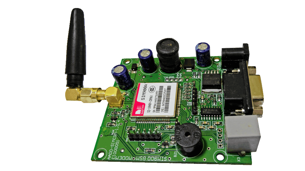
Sim900A GSM Module
Global System for Mobile communication (GSM) is digital cellular system used for mobile devices. It is an international standard for mobile which is widely used for long distance communication.
There are various GSM modules available in market like SIM900, SIM700, SIM800, SIM808, SIM5320 etc.
SIM900A module allows users to send/receive data over GPRS, send/receive SMS and make/receive voice calls.
The GSM/GPRS module uses USART communication to communicate with microcontroller or PC terminal. AT commands are used to configure the module in different modes and to perform various functions like calling, posting data to a site, etc.
For more information about Sim900A and how to use it, refer the topic Sim900A GSM/GPRS Module in the sensors and modules section.
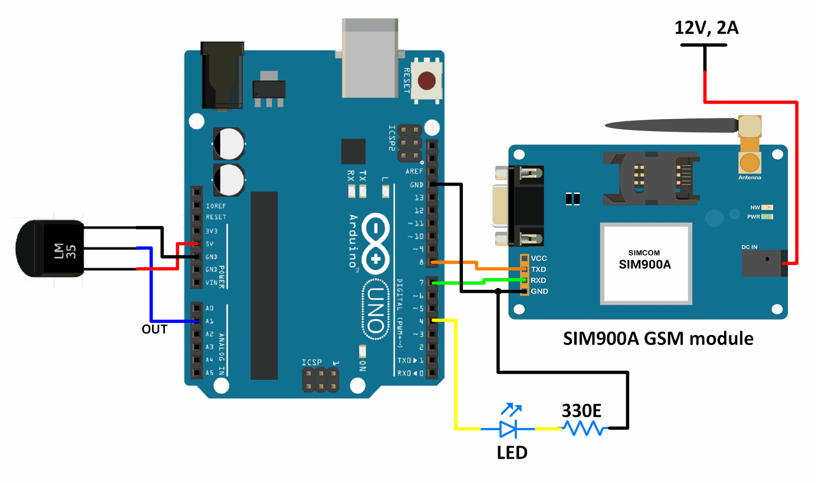
Interfacing Diagram

Interfacing Sim900A GSM Module With Arduino UNO
Example
Monitoring temperature and calling a specific number if the temperature increases beyond a certain value. If a certain message is received within a specified time after the call is placed, then, a fan is turned on (LED turned on for demonstration).
Here, an LM35 is used for measuring the temperature. If the temperature measured is more than 35° C, a call is placed to the number specified and the call is cut after 25 seconds. If the user responds with a “Cool down” message, the fan is turned on (LED turned on for demonstration).
Here, we will be using GPRS_Sim900 library by Seeed-Studio from GitHub.
Extract the library and add it to the libraries folder path of Arduino IDE.
For information about how to add a custom library to the Arduino IDE and use examples from it, refer Adding Library To Arduino IDE in the Basics section.
We have used the header files and the functions from this library to create a simple sketch.
Word of Caution : A small modification needs to be made to the library, otherwise the code will not work in cases where message format is not set to text mode.
We have made the modification in the library we have provided in the attachments section.
If you choose to download the library from the above given link, or from the GitHub page, add the following lines of code in the GPRS_Shield_Arduino.cpp file of the library. Add it in the function named, char GPRS::isSMSunread(). Add the lines of code given below, at the beginning of the function or after the declaration, char *s.
if(!sim900_check_with_cmd(F("AT+CMGF=1\r\n"), "OK\r\n", CMD)) { // Set message mode to ASCII
        return -1;
    }
Sketch
#include <GPRS_Shield_Arduino.h>
#include <SoftwareSerial.h>
#include <Wire.h>

#define PIN_TX    8  /* rx of Arduino (connect tx of gprs to this pin) */
#define PIN_RX    7  /* tx of Arduino (connect rx of gprs to this pin) */
#define BAUDRATE  9600
#define PHONE_NUMBER "98xxxxxx09"
#define MESSAGE_LENGTH 160
char message[MESSAGE_LENGTH]; /* buffer for storing message */
char phone[16];     /* buffer for storing phone number */
char datetime[24];    /* buffer for storing phone number */
int8_t messageIndex = 0;

/* Create an object named Sim900_test of the class GPRS */
GPRS Sim900_test(PIN_TX,PIN_RX,BAUDRATE);

const int8_t lm35_pin = A1;

void setup() {
  Serial.begin(9600); /* Define baud rate for serial communication */
  pinMode(4, OUTPUT);
  while(!Sim900_test.init()) /* Sim card and signal check, also check if module connected */
  {
      delay(1000);
      Serial.println("SIM900 initialization error");
  }
  Serial.println("SIM900 initialization success");
  memset(message, 0, 160);
}

void loop() {
  int16_t temp_adc_val;
  float temp_val;
  temp_adc_val = analogRead(lm35_pin); /* Read temperature from LM35 */
  temp_val = (temp_adc_val * 4.88);
  temp_val = (temp_val/10);
  Serial.print("Temperature = ");
  Serial.print(temp_val);
  Serial.print(" Degree Celsius\n");
    if(temp_val>35)
    {
        Serial.println("Need to cool down");
        Serial.println("Calling to inform");
        Sim900_test.callUp(PHONE_NUMBER); /* Call */
        delay(25000);
        Sim900_test.hangup(); /* Hang up the call */
        int8_t count = 0;
        messageIndex = Sim900_test.isSMSunread(); /* Check if new message available */
              while( (messageIndex < 1) && !strstr( message,"Cool down") ) /* No new unread message */
              {
                  if(count == 5)
                  {
                      messageIndex = Sim900_test.isSMSunread();
                      break;
                  }
                  count++;
                  delay(5000);
                  messageIndex = Sim900_test.isSMSunread();
              }
              while(messageIndex > 0 ) /* New unread message available */
              {
                  Sim900_test.readSMS(messageIndex, message, MESSAGE_LENGTH, phone, datetime); /* Read message */
                    if(strstr( message,"Cool down"))
                    {
                        Serial.println("Turning fan ON");
                        digitalWrite(4, HIGH);
                        memset(message, 0, 160);
                    }
                  messageIndex = Sim900_test.isSMSunread();
              }
        delay(10000);
    }
    else
    {
        Serial.println("Everything is fine");
        digitalWrite(4, LOW);
    }
  delay(3000);
}
Functions Used
1. Sim900_test.readSMS(messageIndex, message, MESSAGE_LENGTH, phone, datetime)
- This function is used to read the message that is present at the location specified by messageIndex.
- MESSAGE_LENGTH is the size of the message that is to be read.
- phone is a character array in which the phone number of the sender of the message is extracted.
- datetime is a character array in which the date and time when the message was received is extracted.
2. GPRS Sim900_test(PIN_TX,PIN_RX,BAUDRATE)
- This is used to create an object named Sim900_test (can have any other valid name according to user) of the class GPRS.
- It also defines the pins on Arduino board that are connected to the Rx and Tx pins of the Sim900A module. It also defines the baud rate used for communicating between the board an module.

No comments:
Post a Comment