XBee S2 (ZigBee) Interfacing with Arduino UNO
Introduction
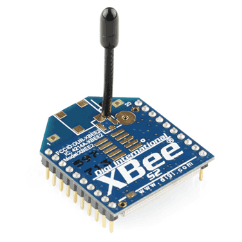
XBee S2 Module
XBee (ZigBee) radios are based on IEEE 802.15.4 (technical standard which defines the operation of low-rate wireless personal area networks (LR-WPANs)) standard and it is designed for point to point, star etc. communication over the air.
ZigBee is an IEEE 802.15.4 based specification for high-level communication protocols used to create personal area networks with low-power digital radios.
Following are the major features of XBee radio devices,
- They work on 2.4 GHz (Unlicensed Radio Band) radio frequency.
- Low data rate (≈250Kbps).
- Low power consumption (1mW, 6mW, 250mW etc.).
- Wireless communication over short distances (90m, 750m, 1mile etc.).
Hence they are used in Home Automation, Wireless Sensor Networks, Industrial Control, Medical Data Collection, Building Automation, etc.
To know more about how Xbee modules work, refer the topic XBee Module in the sensors and modules section.
Interfacing Diagram
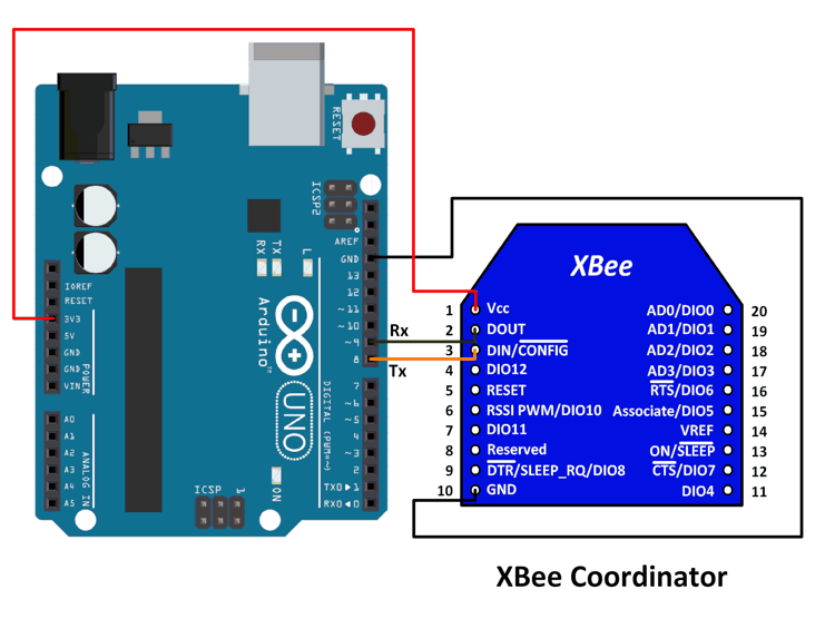
Diagram for XBee Coordinator

Diagram for XBee Router (Or End Device)
Example
Here, we have connected an XBee S2 to Arduino UNO. This XBee is configured as a Coordinator in API mode with API enable set to 1(you can use API enable set to 2 as well, it will use escape characters along with the data).
SoftwareSerial of Arduino is used for communication with XBee. Serial of Arduino is used to display the received data on the serial monitor.
Another XBee device is configured as a Router in API mode with API enable set to 1(you can use API enable set to 2 as well, it will use escape characters along with the data). Use the same API enable setting for both XBee devices. (You can also configure this device as an End Device in API mode).
A switch is connected to pin DIO1 (pin 19 on the module) of the Router (or End Device) XBee module and the pin is configured as a Digital Input.
A potentiometer is given 1.2V and ground to its fixed terminals and the variable terminal of the potentiometer is connected to pin AD2 (pin 18on the module) of the Router (or End Device) XBee module and the pin is configured as an Analog Input.
IO Sampling (IR) rate can be set according to the requirement of the application, 100 msec for example.
All the configurations and settings are done using X-CTU software provided by Digi International.
If you don’t know how to configure XBee modules using X-CTU, refer the sub-topic XBee Configuration in the topic XBee Module in the sensors and modules section.
The Router (or End Device) XBee module sends the IO samples of the potentiometer and the switch periodically depending on the IR setting. This data is received by the coordinator and the Sketch uploaded in the Arduino parses the data received and extracts the IO samples information from it.
This is displayed on the serial monitor so that working can be verified.
Here, we will be using Andrew Rapp’s XBee library for Arduino from GitHub.
Extract the library and add it to the libraries folder path of Arduino IDE.
For information about how to add a custom library to the Arduino IDE and use examples from it, refer Adding Library To Arduino IDE in the Basics section.
Here, we have created a sketch by modifying the example sketch given by the Author for receiving IO sample for S2 modules. The modifications basically interchange the Serial ports used for communication and debugging in order to avoid having to use an extra device for debugging.
Sketch
#include <XBee.h>
#include <SoftwareSerial.h>

#define ssRX  9 /* Rx pin for software serial */
#define ssTX  8 /* Tx pin for software serial */

/* Create object named xbee_ss of the class SoftwareSerial */
SoftwareSerial xbee_ss(ssRX, ssTX); /* Define pins for software serial instance named xbee-ss(any name of your choice) to be connected to xbee */
/* ssTx of Arduino connected to Din (pin 3 of xbee) */
/* ssRx of Arduino connected to Dout (pin 2 of xbee) */

XBee xbee = XBee(); /* Create an object named xbee(any name of your choice) of the class XBee */

ZBRxIoSampleResponse ioSamples = ZBRxIoSampleResponse();
/* Create an object named ioSamples(any name of your choice) of the class ZBRxIoSampleResponse */

void setup() {
  Serial.begin(9600); /* Define baud rate for serial communication */
  xbee_ss.begin(9600); /* Define baud rate for software serial communication */
  xbee.setSerial(xbee_ss); /* Define serial communication to be used for communication with xbee */
  /* In this case, software serial is used. You could use hardware serial as well by writing "Serial" in place of "xbee_ss" */
  /* For UNO, software serialis required so that we can use hardware serial for debugging and verification */
  /* If using a board like Mega, you can use Serial, Serial1, etc. for the same, and there will be no need for software serial */
}

void loop() {
  xbee.readPacket(); /* Read until a packet is received or an error occurs */

  if(xbee.getResponse().isAvailable()) /* True if response has been successfully parsed and is complete */
  {
    if(xbee.getResponse().getApiId()==ZB_IO_SAMPLE_RESPONSE) /* If response is of IO_Sample_response type */
    {
      xbee.getResponse().getZBRxIoSampleResponse(ioSamples); /* Get the IO Sample Response */

      Serial.print("Received I/O Sample from: ");

      Serial.print(ioSamples.getRemoteAddress64().getMsb(), HEX); /* DH(in HEX format) of the sending device */
      Serial.print(ioSamples.getRemoteAddress64().getLsb(), HEX); /* DL(in HEX format) of the sending device */
      Serial.println("");

      if (ioSamples.containsAnalog()) { /* If Analog samples present in the response */
        Serial.println("Sample contains analog data");
      }

      if (ioSamples.containsDigital()) { /* If Digital samples present in the response */
        Serial.println("Sample contains digtal data");
      }

      /* Loop for identifying the analog samples present in the received sample data and to print it */
      for (int i = 0; i <= 4; i++) { /* Only 4 Analog channels */
        if (ioSamples.isAnalogEnabled(i)) { /* Check Analog channel mask to see if the any pin is enabled for analog input sampling */
          Serial.print("Analog (AI");
          Serial.print(i, DEC);
          Serial.print(") is ");
          Serial.println(ioSamples.getAnalog(i), DEC);
        }
      }

      for (int i = 0; i <= 12; i++) { /* 12 Digital IO lines */
        if (ioSamples.isDigitalEnabled(i)) { /* Check Digital channel mask to see if any pin is enabled for digital IO sampling  */
          Serial.print("Digital (DI");
          Serial.print(i, DEC);
          Serial.print(") is ");
          Serial.println(ioSamples.isDigitalOn(i), DEC);
        }
      }
    }
    else
    {
      Serial.print("Expected I/O Sample, but got ");
      Serial.print(xbee.getResponse().getApiId(), HEX); /* Print response received instead of IO_Sample_Response */
    }
  }
  else if (xbee.getResponse().isError()) { /* If error detected, print the error code */
    Serial.print("Error reading packet.  Error code: ");
    Serial.println(xbee.getResponse().getErrorCode());
  }
}
No comments:
Post a Comment